Overview Summary
- Incomplete die cut specifications are one of the most common causes of rejected parts and production delays.
- Tolerance callouts should reflect actual functional requirements, not arbitrary precision.
- Material callouts must include thickness, adhesive, liner, and performance requirements.
- Good prints define critical dimensions, datums, and inspection criteria clearly.
- Early collaboration with your converter helps prevent tooling issues and costly revisions.
- A strong specification turns your die cutter into a manufacturing partner, not just an order taker.
 When a die cut part fails inspection, the problem is often blamed on tooling, production, or material quality.
But in many cases, the root cause starts much earlier, with the print.
An incomplete or ambiguous die cut specification creates uncertainty. When details are not clear, assumptions are made, and variations occur. This ultimately leads to rework, scrap, delayed launches, and frustrated engineering teams.
Whether you are sourcing foam gaskets, pressure-sensitive adhesive components, films, tapes, seals, or insulating materials, the quality of your specification directly impacts the quality of your parts.
The good news is that many rejected parts can be prevented with better print documentation.
Here is what every usable die cut specification should include.
Why Die Cut Specifications Matter More Than Many Teams Realize
Die cutting is often viewed as simple because the finished part may look simple. A gasket, spacer, tape strip, or foam insert may appear to be nothing more than a shape cut from material.
In reality, converting flexible materials introduces manufacturing variables such as:
- Material compression
- Adhesive flow
- Liner movement
- Stretch during processing
- Tool wear over time
- Slitting and roll tolerance variation
Unlike rigid machined parts, flexible die cut materials do not always behave predictably. That means the print needs to communicate not just shape, but function.
A strong specification answers three critical questions:
- What material is required?
- What dimensions truly matter?
- What variation is acceptable?
If any of these are unclear, defects become more likely.
Start with Clear Material Callouts
One of the biggest specification mistakes is using vague material descriptions. Examples of weak callouts include:
- Foam gasket
- Acrylic tape
- Rubber pad
- PET film
These descriptions are not precise enough for manufacturing. A proper material callout should include all relevant construction details.
Material Callout Checklist
Include:
- Material manufacturer (if required)
- Material grade or part number
- Thickness
- Density or durometer (when relevant)
- Adhesive type
- Liner type
- Color
- Special coatings or laminations
- Performance requirements (temperature, chemical resistance, compression set, dielectric properties, etc.)
For example, instead of writing:
- 1/16″ foam with adhesive
Use something like:
- 0.062″ closed-cell EPDM foam, 6 lb density, laminated with 3M 9472LE adhesive, 58 lb polycoated kraft liner
That level of detail eliminates guesswork. It also helps your converter identify possible issues before production begins.
Tolerance Callouts Should Reflect Function
Not every dimension needs the same tolerance. This is one of the most common print problems.
Engineering teams sometimes apply extremely tight tolerances across every feature, even when only a few dimensions actually affect performance.
For example:
- Outer profile may only need ±0.020″
- Mounting hole spacing may require ±0.005″
- Seal width may need ±0.010″
If everything is held to the tightest tolerance:
- Tooling becomes more expensive
- Yield may decrease
- Lead times may increase
- Costs go up unnecessarily
The better approach is to identify critical-to-function dimensions, then call out tolerances accordingly.
Ask:
- Which dimensions affect fit?
- Which dimensions affect sealing?
- Which dimensions affect assembly?
- Which dimensions are cosmetic only?
Common Flexible Material Tolerance Ranges
Actual achievable tolerance depends on material type, thickness, and geometry, but general ranges often look like:
- Rotary die cutting: ±0.010″ to ±0.020″
- Steel rule die cutting: ±0.005″ to ±0.015″
- Laser cutting: can be tighter for certain geometries
- Kiss cutting of adhesive materials: depends heavily on the liner and adhesive construction
Very soft foams or stretchy materials may require looser tolerances.
Rigid films may allow tighter control.
This is why material selection and tolerance planning should happen together.
Define Critical Dimensions Clearly
A print overloaded with dimensions can be just as problematic as one with too few. What matters most is clarity. A usable print should identify:
- Overall length and width
- Hole diameters
- Slot dimensions
- Corner radii
- Cut through or kiss cut
- Adhesive zones
- Removed liner areas
- Registration requirements
Be especially clear about which features are critical.
Helpful methods include:
- Flagging critical dimensions
- Using datum references
- Applying GD&T when appropriate
- Adding notes for inspection requirements
If your team has specific go/no-go criteria, include those as well. The easier it is to inspect a part, the easier it is to maintain quality.
Don’t Overlook Construction Details
Many rejected parts are dimensionally correct but still unusable because the construction was not fully specified.
Examples include:
- Adhesive on wrong side
- Incorrect liner split
- Wrong release liner orientation
- Missing pull tabs
- Wrong roll direction
- Incorrect stack orientation
- Part-to-part nesting issues
Include notes such as:
- Adhesive applied to side A
- Finger lift on left edge
- Parts supplied on rolls
- Maximum roll OD: 14″
- Core ID: 3″
- Parts wound adhesive side in
- Sheets stacked with liner facing up
This information often determines whether or not a part works on the production floor.
Include the Intended Application
This valuable piece of information is too often left off of specifications. Many buyers hesitate to share application details because they assume the converter only needs the print.In reality, context helps prevent mistakes.
Tell your converter what the part does. Examples include:
- Seals electronics enclosure against moisture
- Dampens vibration in appliance assembly
- Electrically insulates battery components
- Bonds trim panel to metal housing
- Shields sensitive electronics from EMI/RFI interference
Application context helps identify hidden risks, such as:
- Material creep
- Compression failure
- Adhesive incompatibility
- Heat degradation
- Chemical exposure
Sometimes the print looks fine, but the application reveals a better material or design. That kind of insight only happens when the supplier understands the end use.
Prototype Before Full Production
Even the best print benefits from validation. Prototyping helps answer practical questions such as:
- Does the part install easily?
- Does the adhesive bond properly?
- Does the foam compress as expected?
- Are tolerances realistic?
- Does the liner release cleanly?
Prototype runs often uncover issues that CAD alone cannot predict. Common discoveries include:
- Tolerances tighter than necessary
- Material thicker than expected
- Adhesive too aggressive or too weak
- Geometry difficult to assemble
Finding these issues early is far less expensive than discovering them during production.
What Makes a Die Cutting Partner Different from a Vendor?
A vendor fulfills a print, and a technical partner improves it. That difference matters when tolerances are tight, materials are complex, or assemblies are high volume.
For Thrust Industries, the goal is not simply to cut parts to print. Our team works with customers to evaluate:
- Material performance
- Tolerance feasibility
- Tool design
- Manufacturability
- Prototype optimization
- Production scalability
That collaborative approach helps customers reduce:
- Rework
- Scrap
- Production delays
- Supplier-related quality issues
For engineering and procurement teams under pressure to hit launch timelines, having an experienced converting partner can significantly reduce risk.
Better Prints Lead to Better Parts
A good die cut specification does more than define geometry; it creates alignment between engineering, procurement, quality, and manufacturing. Before releasing a print, make sure it includes:
- Complete material callout
- Functional tolerance requirements
- Critical dimensions
- Construction details
- Packaging requirements
- Application context
The more clearly your requirements are defined, the more likely you are to get parts that perform correctly the first time.
If you are developing a new die cut component or struggling with recurring quality issues, contact Thrust Industries to discuss your application. Their team can help evaluate materials, tolerances, and manufacturability so your next part arrives ready for production.
 How Advanced Foams and Films Are Changing Electronics Enclosures
  What to Know About Global Supply Chain Risks for Precision Die-Cut Components
  Thrust Industries Expands Capabilities with New Cutting Technology
 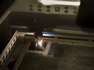 What’s the Difference Between Die Cutting and Laser Cutting?
  Step-by-Step: Understanding the Custom Die Cutting Process